It is sold at a price of up to 50% of the new one, depending on the required list of services (installation, delivery, commissioning).
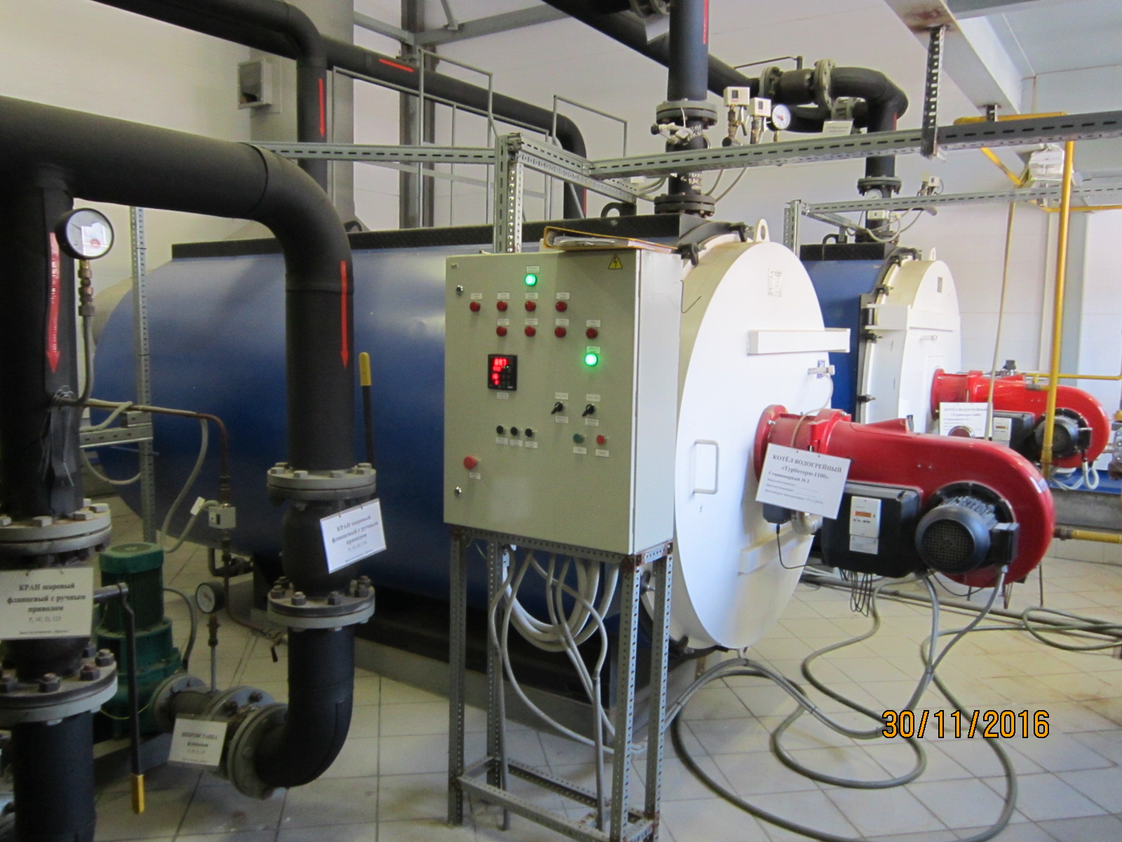
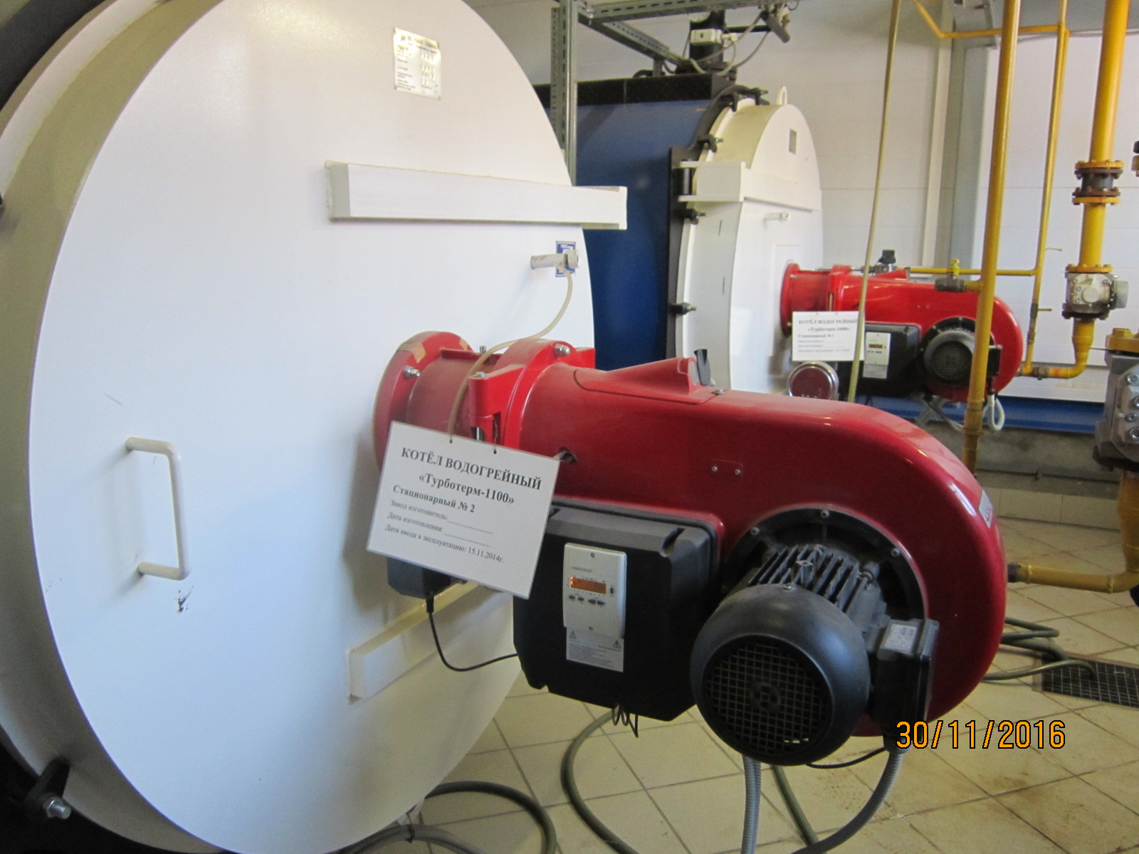
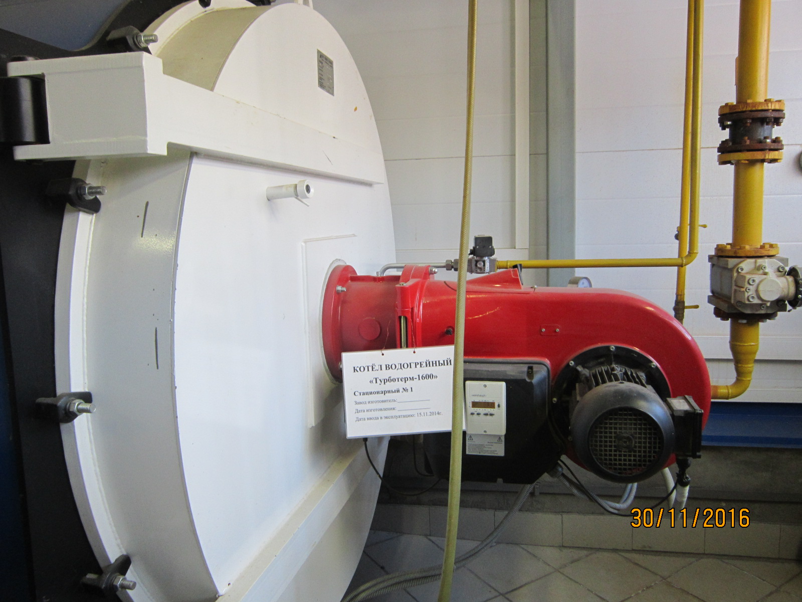
The Turboterm 1600 gas-fired boiler is equipped with an automated WG 20/2-A, 1 1/2 ” type gas burner, type ZM manufactured by Weishaupt (Germany) with a combustion control box (TAG) W- MF 50. The Turboterm 1100 gas-fired boiler is equipped with an automated WG 20/2-A, 1 ” type gas burner, type ZM, manufactured by Weishaupt (Germany) with a combustion control box (TAG) W- MF 50.
Boiler equipment is controlled using the logical modules LOGO! Basic ”(Siemens”), digital program control controller “MC12” (“MZTA” OJSC), which together with electrical equipment and sensors ensure the boiler room operation in optimal mode, provide protection against emergency situations and issue light alarms with indication of emergency parameters.
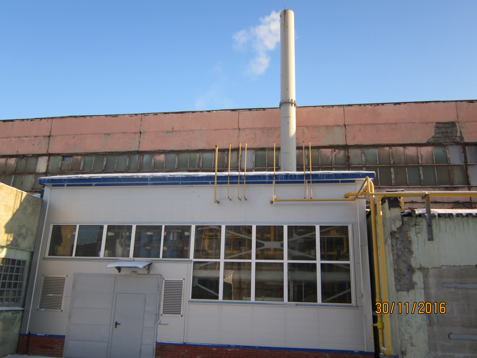
In October-December 2014. commissioning work on instrumentation and automation of two water-heating boilers “Turboterm 1600” and “Turboterm 1100” (REMEX) with a total capacity of 2.7 MW, running on gas, to obtain hot water for heating and technology were carried out.
The fuel used is gas. Location – Moscow region.
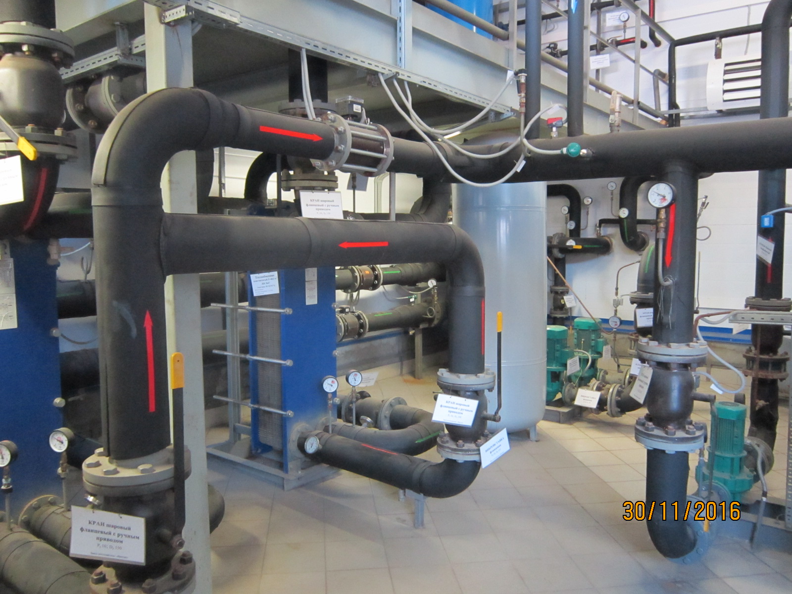
Gas supply to the boilers is carried out with the GRU installed inside the boiler room. The gas pressure at the boiler room inlet is <0.6 MPa, and with the outlet pressure after the GRU is 0.030 MPa.
Commissioning work on instrumentation and automation was carried out in accordance with the standard methodological guidelines for setting up automatic control systems.
The operation of the boiler house was discontinued in 2017 due to the suspension of the enterprise. A photo:


DESCRIPTION AND TECHNICAL CHARACTERISTICS OF THE INSTRUMENTATION SYSTEM and A.
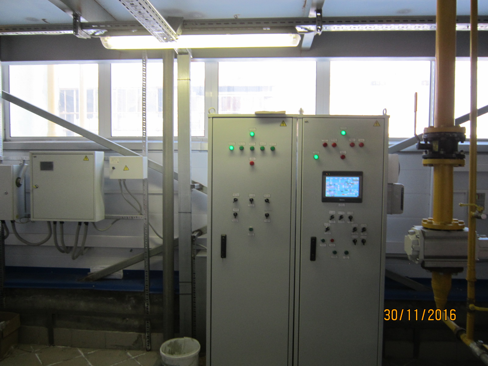
The safety and control automation of the boiler room includes 5 cabinets and control devices: ША (automatic control cabinet), ШС (alarm cabinet), ШСС (power control cabinet), ШК1 and ШК2 (boiler control cabinets No. 1 and No. 2, respectively) and two managers combustion W-FM 50 burner control.
1. Boiler board 1 (boiler board 2).
Boiler panel 1 (boiler panel 2) provides the following functions:
• power supply for the W-FM50 combustion manager and the Weishaupt WMG20 / 2-A burner fan motor;
• control of the burner power (by means of the TPM148 regulator);
• burner ignition control
• control of the boiler circuit pump 1M1 (2M1):
• protection and signaling of boiler alarm parameters is provided by the logical module LOGO! Basic:
– when the temperature of the water leaving the boiler is exceeded;
– at minimum water pressure in the boiler;
– at maximum water pressure in the boiler;
– at low vacuum in the boiler;
– at low water consumption through the boiler;
– when the voltage disappears;
• stopping the fuel supply to the burner is ensured by the combustion manager W-FM 50:
– if during ignition the signal about the presence of flame is not received from the photosensor;
– if, during operation, a signal is received about the extinction of the flame, as well as in the event of an open or short circuit in the photosensor circuit;
– in case of overload or short. in the power circuit of the burner fan motor;
– in case of insufficient air pressure drop across the burner;
– in case of insufficient gas pressure in front of the gas valve block;
– at high gas pressure in front of the gas valve block;
– in case of leaking valves
2. Automation cabinet (ША).
An operator panel is installed in the automatic control cabinet to inform the operator about the progress of the boiler room and control the system parameters.
The control cabinet has the ability to control:
• valves for making up the boiler circuit, heating and hot water supply;
• heating temperature;
• DHW supply temperature;
• heating pumps in automatic mode;
• DHW pumps in automatic mode;
• fans of two air heating units in automatic mode, depending on the temperature in the boiler room.
• solenoid gas valve
The following alarms are output to the control cabinet:
– emergency water pressure;
– emergency gas pressure;
– excess concentration of carbon monoxide CO (100mg / m³ = 85.8ppm):
– excess of CH4 methane concentration (10% LEL):
– fire
There is also a VKT-7 heat calculator in the automation cabinet. The heat meter is designed to measure and record the parameters of the heat carrier (temperature, pressure, flow), the amount of the heat carrier and the amount of heat (thermal energy) in water heat supply systems.
3. Alarm cabinet.
A 4-channel Seitron RGY 000 MBP4 signaling device (items 4-5) with external sensors is installed in the cabinet, which provides control of the gas content in the boiler room.
The content of carbon monoxide in the workshop is controlled by one CO sensor
SGY CO0 V4NC type (p. 4-3);
Control over the content of combustible gases is carried out:
Above the boiler burners, one СН4 sensor of the SGY ME0 V4NC type (p. 4-1);
In the GRU, one СН4 sensor of the SGY ME0 V4NC type (p. 4-2)
Alarms about excess concentration are transmitted to the automatic control cabinet (ША).
4. Power control cabinet (SHSU)
The ShSU power control cabinet performs the following functions:
• control of heating pumps (3M1, 3M2), including automatic pressure maintenance in the direct pipeline of network water;
• control of DHW pumps (5M1, 5M2);
• control of the feed pump (4M);
• indication of pump activation;
• indication in case of an emergency of one of the pumps;
• checking the indicator lamps.
5. System for collecting and processing information “ELEX 2051”.
“ELEX 2051” consists of a controller of the object “ELEX 2051 o”, installed near the ShchA and a controller of the dispatcher “ELEX 2051 d”, installed in the security room.
The controller of the “ELEX 2051 o” object installed in the boiler room reads information from sixteen alarms.
- 1 channel – boiler no. 1 failure;
- 2 channel – boiler no. 2 failure;
- Channel 3 – minimum air temperature in the boiler room;
- 4 channel – emergency water pressure;
- 5 channel – failure of pumps (network, hot water supply or make-up);
- 6 channel – emergency gas pressure at the outlet from the GRU;
- 7 channel – gas contamination of the room with combustible gas;
- Channel 8 – carbon monoxide gas pollution in the room;
- Channel 9 – fire signal;
- Channel 10 – the gas shut-off valve is closed;
- 11channel – penetration
- 12channel – reserve;
- Channel 13 – reserve;
- Channel 14 – reserve;
- Channel 15 – reserve;
- Channel 16 – reserve;
Further, the data is pre-processed and transferred to the dispatcher controller.
Boiler room specification 2.7 MW
